Section 15 · Pages 80–87 (8 pages)
Hydra-Matic Drive: Control Valve, Parking Brake and Installation
From the 1951 Cadillac Shop Manual Supplement
Disassembly, inspection and assembly of the control valve, with an exploded valve body key naming the shifter valves, regulator plugs, front servo exhaust valve and transition valve. It also covers the parking brake bracket with its blocker pistons, governor to sleeve clearance, side cover, oil pan, torus check valve and flywheel, installing the transmission in the car, and removal and installation of the steering column manual controls.
Read this section free, starting at page 80What this section covers
- Control valve overhaul
- Valve body parts key
- Parking brake bracket overhaul
- Torus cover and flywheel inspection
- Transmission installation
- Manual controls on the steering column
- Year
- 1951
- Make
- Cadillac
- Type
- Service Manual, Supplement
- Models
- Series 61, 62, 60 Special, 75 and 86 Commercial Chassis; 331 cu. in. V-8
- Pages
- 113
What’s inside
Service supplement
- Cover, Craftsman Code and ContentsCover, title page of the Cadillac Service Department, the Cadillac Craftsman Code and Certified Craftsman's League, and the section contents list.pp. 1–4
- 1General InformationForeword explaining use with the 1950 Shop Manual, a table of the 1951 series with bore, stroke, wheelbase and starting engine numbers, and the locations of engine serial, engine unit, body and Hydra-Matic numbers.pp. 5–6
- 2Lubrication and Preventive Maintenancepp. 7–13
- 3Bodypp. 14–25
- 4Chassis Sheet MetalThe new five-piece front bumper assembly with its removal, disassembly and installation torques, and the hood lock release lever below the grille.pp. 26–26
- 5FrameX-type frame description, body bolt locations by body style with torque values, and a frame checking dimension chart for every series.pp. 27–28
- 6Chassis SuspensionChanges in spring heights and the relocated eccentric bushing hex end, adjusted from the front with Tool J-4691.pp. 29–29
- 7SteeringSteering gear notes, with changes to steering column removal and installation caused by the 1951 instrument panel design.pp. 30–30
- 8Rear AxleRear axle gear ratios for each 1951 series (3.36, 3.77 and 4.27 to 1) and their identification marks on the axle case.pp. 31–31
- 9BrakesThe new mechanical stoplight switch and self-adjusting slipper anchor on Series 61, 62 and 60 Special, with minor and major brake adjustment and stoplight switch replacement.pp. 32–33
- 10Engine MechanicalChanges to the 331 cu. in. V-8 (redesigned pistons, valve guides without counterbores), valve guide installation with Tool J-3066 adapters and piston pin removal and installation with Tool J-3848.pp. 34–35
- 11Engine ElectricalA one-page note that 1950 Shop Manual engine electrical information applies to 1951 cars.pp. 36–36
- 12Engine Fuel and Exhaustpp. 37–43
- 13Engine Cooling; Clutch and Synchro-Mesh TransmissionSections 13 and 14 share one page, each referring to the 1950 Shop Manual for cooling system, clutch and Synchro-Mesh service.pp. 44–44
- 15Hydra-Matic Drive: Description and Diagnosispp. 45–54
- 15Hydra-Matic Drive: On-Car Service and Removalpp. 55–59
- 15Hydra-Matic Drive: Disassembly and Inspectionpp. 60–69
- 15Hydra-Matic Drive: Unit Assembly, Pumps, Governor and Servospp. 70–79
- 15Hydra-Matic Drive: Control Valve, Parking Brake and Installationpp. 80–87
- 16Chassis Electricalpp. 88–93
- 17AccessoriesStandard and automatic heating systems with the rear window defogging blower, Signal-Seeking radio fader and foot tuning switch, push-button radio and fog lamp switch locations.pp. 94–94
Specifications, torques and tools
- 18Specificationspp. 95–105
- 19Torque TightnessesTorque tables by bolt location and size for body, frame and bumpers, suspension, steering, rear axle, brakes, engine, fuel and exhaust, cooling, clutch, Hydra-Matic and sheet metal.pp. 106–108
- 20Special Toolspp. 109–113
Other manuals for this vehicle
 1940Parts Catalog1940–1956 GM Hydra-Matic Transmission Parts Catalog (1956 Edition)Bulletin 37A-100 (A-3700)
 1946Service Manual1946–1955 General Motors Hydra-Matic On-the-Car Adjustment Service ManualJ 6372
 1945Service Bulletin1947 GM Product Service Bulletin – November 1947 Issue
 1946Service Bulletin1948 GM Product Service Bulletin – April 1948 Issue
 1946Service Bulletin1948 GM Product Service Bulletin – August 1948 Issue
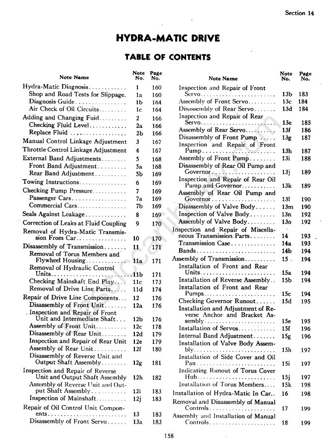 1950Service Manual1950 Cadillac Shop Manual – Hydra-Matic Section
 1955Parts Catalog1956 GM Automatic Transmission Parts Catalog SupplementA-3010-A