Section 1 · Pages 3–8 (6 pages)
Hydra-Matic Diagnosis
From the 1950 Cadillac Shop Manual – Hydra-Matic Section
A general description of the 1950 Cadillac Hydra-Matic, then shop and road tests for slippage: neutral, first speed stall (1,500–1,700 rpm), reverse, second and third speed tests with a table of which band or clutch affects which gears. The Cadillac Hydra-Matic Diagnosis Guide lists shift conditions with first to fifth operations and flat-rate codes, with oil leak and noise charts and shift point tables for 1946–1950 and 1941–1942 cars. Closes with the air check of the eleven case oil passages using tool J-4353 and a visual check of clutch hydraulics.
Read this section free, starting at page 3What this section covers
- Stall and road tests for band and clutch slippage
- Diagnosis guide with flat-rate operation codes
- Oil leak and noise diagnosis charts
- Upshift and downshift speed tables
- Air check of oil circuits
- Visual air check of clutch hydraulics
- Year
- 1950
- Make
- Cadillac
- Type
- Service Manual
- Models
- Series 61, 62, 60S and 75 passenger cars; Series 86 commercial chassis
- Pages
- 42
What’s inside
Hydra-Matic Drive (Section 14)
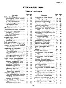
- Contents and Cross SectionThe Section 14 table of contents listing every note with its book page, followed by the Fig. 169 cross section of the Hydra-Matic Drive with numbered parts.pp. 1–2
- 1Hydra-Matic Diagnosispp. 3–8
- Fluid, Linkage and Band Adjustmentspp. 9–12
- Fluid Coupling Leaks and Transmission RemovalLocating and correcting leaks at the flywheel, torus cover, front oil seal and front pump cover (Fig. 181), and the first steps of removing the Hydra-Matic from the car with hoist J-1636B and engine support J-3068; the removal steps continue on the next page.pp. 13–13
- 11Disassembly of Transmissionpp. 14–18
- 12Repair of Drive Line Componentspp. 19–25
- 13Repair of Oil Control Unit Componentspp. 26–35
- 14Inspection of Miscellaneous Transmission PartsCleaning and checking the transmission case oil passages, with the Fig. 227 passage chart, and inspection of the front and rear bands; the end of valve body assembly is on the same page.pp. 36–36
- 15Assembly of Transmissionpp. 37–40
- Installation in Car and Manual ControlsInstalling the torus members and the transmission in the car, with torus cover dowel alignment, bolt torques and refill with about 12 quarts, then removal, disassembly, assembly and installation of the steering column manual controls, selector lever and neutral switch.pp. 41–42
Other manuals for this vehicle
 1940Parts Catalog1940–1956 GM Hydra-Matic Transmission Parts Catalog (1956 Edition)Bulletin 37A-100 (A-3700)
 1946Service Manual1946–1955 General Motors Hydra-Matic On-the-Car Adjustment Service ManualJ 6372
 1945Service Bulletin1947 GM Product Service Bulletin – November 1947 Issue
 1946Service Bulletin1948 GM Product Service Bulletin – April 1948 Issue
 1946Service Bulletin1948 GM Product Service Bulletin – August 1948 Issue
 1951Service Manual1951 Cadillac Shop Manual Supplement
 1955Parts Catalog1956 GM Automatic Transmission Parts Catalog SupplementA-3010-A