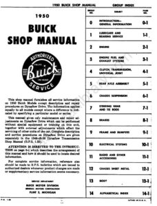
Section 4-B · Pages 78–94 (17 pages)
Synchromesh Transmission and Universal Joint
From the 1950 Buick Shop Manual
The three-speed synchromesh transmission and universal joint: specifications, description, the column shift control and selector mechanism, shift control adjustment, torque ball adjustment, removal and installation, and complete disassembly, cleaning, inspection and assembly with exploded views.
Read this section free, starting at page 78What this section covers
- Transmission and universal joint specifications
- Shift control mechanism
- Shift control adjustment
- Torque ball adjustment
- Removal and installation
- Disassembly, inspection and assembly
- Year
- 1950
- Make
- Buick
- Vehicle
- Passenger Cars
- Type
- Service Manual
- Models
- Special Series 40, Super Series 50, Roadmaster Series 70 (Models 41–46S, 51–59, 71–79)
- Publication
- P.S. 1.33
- Pages
- 366
What’s inside
Shop manual
- 0Introduction and General Informationpp. 3–9
- 1-ALubricare Instructionspp. 10–17
- 1-BBearing Service (Ball and Roller)pp. 18–21
- 2-AEngine Specificationspp. 22–28
- 2-BEngine Descriptionpp. 29–36
- 2-CEngine Tune Up and Trouble Diagnosispp. 37–41
- 2-DCylinder Head and Valve Mechanism Servicepp. 42–49
- 2-ECrankshaft and Connecting Rod Bearings, Pistons and Ringspp. 50–58
- 2-FCooling and Oiling Systems Servicepp. 59–64
- 2-GEngine Mountings, Flywheel and Housingpp. 65–69
- 4-AClutch (Series 40–50)pp. 70–77
- 4-BSynchromesh Transmission and Universal Jointpp. 78–94
- 4-CDynaflow Transmissionpp. 95–101
- 5-ARear Axle Specifications and Descriptionpp. 102–105
- 5-BRear Axle Trouble Diagnosispp. 106–109
- 5-CRear Axle Removal and Disassembly Procedurespp. 110–125
- 6-AChassis Suspension Specifications and Descriptionpp. 126–133
- 6-BChassis Suspension Trouble Diagnosispp. 134–139
- 6-CChassis Suspension Repair Operationspp. 140–148
- 6-DWheel Balance and Alignmentpp. 149–155
- 7Steering Gear and Tie Rodspp. 156–167
- 8-CBrake Service and Adjustment (first page only)The opening page of section 8-C: its contents list, filling the master cylinder with Delco Super No. 11 fluid and the start of brake bleeding. The rest of Group 8 is not in this scan.pp. 168–168
- 9Frame and Bumperspp. 169–176
- 10-AElectrical Specificationspp. 177–180
- 10-BElectrical Trouble Diagnosispp. 181–186
- 10-CBattery and Cablespp. 187–195
- 10-DGenerating Systempp. 196–211
- 10-ECranking (Starter) Systempp. 212–228
- 10-FIgnition Systempp. 229–245
- 10-GLighting Systempp. 246–253
- 10-HSignal Systemspp. 254–263
- 10-IInstruments and Clockpp. 264–268
- 10-JWiring Circuit Diagramspp. 269–280
- 11-AAccessories Other Than Radiopp. 281–287
- 11-BRadiopp. 288–308
- 13-ABody Introduction, Care of Body, Compounds and Mountingspp. 309–314
- 13-BDoors and Compartment Lidspp. 315–322
- 13-CWindshield Wipers, Glass and Ventilatorspp. 323–338
- 13-DInterior Trim and Seatspp. 339–344
- 13-EConvertible Coupe Bodiespp. 345–349
- 13-FHydro-Lectric Power Systempp. 350–360
Index
- 14Alphabetical IndexAlphabetical subject index with group page numbers. It still lists entries for Groups 3, 8 and 12, which are not in this scan.pp. 361–366
Other manuals for this vehicle
 1929Specifications1929 Buick Detailed Specifications
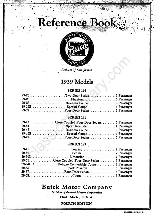 1929Owner's Manual1929 Buick Reference Book (Owner’s Manual)
 1933Service Manual1933 Buick Shop Manual
 1934Service Manual1934 Buick Series 40 Shop ManualBPS-1.19
 1934Service Manual1934 Buick Series 50 60 90 Shop ManualBPS-1.18
 1940Parts Catalog1940-1972 Buick Chassis and Body Illustration Catalog
 1940Parts Catalog1940–1955 GM Automatic Transmission Parts Catalog A-3010A-3010
 1942Service Manual1942 Buick Shop ManualBPS-1.27