Section 13-9 · Pages 12–47 (36 pages)
Description and Operation
From the 1967 Buick Automatic Climate Control (ACC) System Manual
Division II. It explains how the three sensors and power element lever balance in-car temperature against the temperature set at the panel, describes each thermomechanical and program component, and covers the operation of the selector and temperature levers. Layout drawings, vacuum hose charts and electrical circuit diagrams show each operating mode.
Read this section free, starting at page 12What this section covers
- Sensors and power element assembly
- Hot and cold vacuum nozzles and vacuum regulator
- Temperature door actuator and program vacuum disc switch
- Thermostatic vacuum valve and master switch
- Blower and compressor ambient switches
- Selector lever positions: LOW, HIGH, DE-FOG, DE-ICE
- Vacuum and electrical circuit diagrams
- Year
- 1967
- Make
- Buick
- Type
- Service Manual
- Models
- 45000, 46000, 48000 and 49000 series
- Pages
- 73
What’s inside
Contents
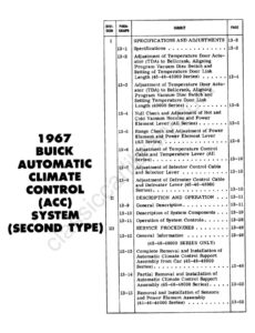
- ContentsTitle page and contents listing for the four divisions, with paragraph numbers 13-1 to 13-33 and page numbers.pp. 1–3
Specifications and adjustments
Description and operation
- 13-9Description and Operationpp. 12–47