Section 3 · Pages 76–93 (18 pages)
Group 3: Carburetors
From the 1961 Ford and Mercury Truck 850–1100 Series Shop Manual
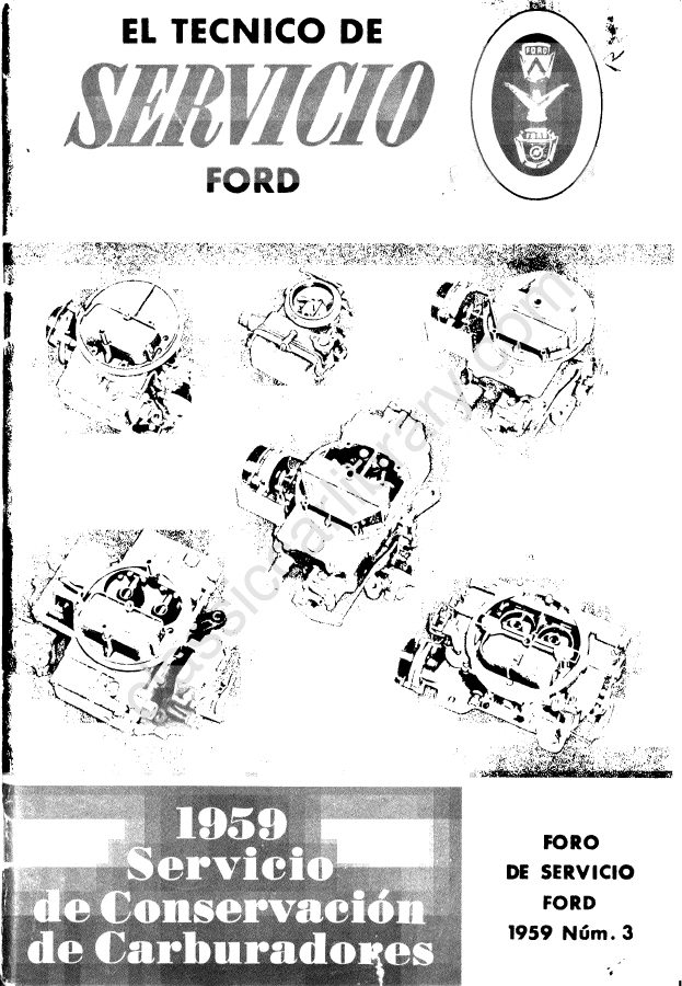
Part 3-2 is the carburetor repair section. It includes removal, cleaning and inspection, and overhaul of the dual and four-barrel carburetors, with float settings, metering blocks, jets, fuel enrichment valve, idle adjusting needles and the balance tube O-ring seal.
Read this section free, starting at page 76What this section covers
- Carburetor removal and installation
- Cleaning and inspection
- Dual carburetor overhaul
- Four-barrel carburetor overhaul
- Float adjustment
- Metering blocks and jets
- Idle adjusting needles
- Year
- 1961
- Vehicle
- Heavy Duty Trucks, Trucks
- Type
- Service Manual
- Models
- 850–1100 Series F, C, T, H trucks; 401, 477, 534 Super Duty V-8 (no diesel)
- Pages
- 309
What’s inside
Front matter
Service groups
- 1Group 1: Engines and Exhaust Systempp. 9–49
- 2Group 2: Ignition System Maintenancepp. 50–58
- 2Group 2: Distributor and Governorpp. 59–65
- 3Group 3: Fuel System Maintenancepp. 66–75
- 3Group 3: Carburetorspp. 76–93
- 3Group 3: Fuel Pump, Tank and LinesPart 3-3 covers the fuel pump, fuel tank replacement and fuel line replacement.pp. 94–96
- 3Group 3: Fuel System SpecificationsPart 3-4 lists fuel system specifications, including carburetor clearances and fuel pump data.pp. 97–97
- 4Group 4: Cooling System Maintenancepp. 98–106
- 4Group 4: Water PumpPart 4-2 covers water pump removal and installation, and disassembly and assembly, on F-, T-, C- and H-series trucks, including the sealed shaft and bearing and the bleed hole in the housing.pp. 107–108
- 4Group 4: Cooling System SpecificationsPart 4-3 gives the cooling system specifications that close Group 4.pp. 109–109
- 5Group 5: Clutches and Manual Transmissionspp. 110–136
- 5Group 5: Auxiliary Transmissionspp. 137–150
- 5Group 5: Gear Shift Linkage and Specificationspp. 151–157
- 6Group 6: Rear Axles and Drive Linespp. 158–225
- 7Group 7: Front Wheel AlignmentPart 7-1 covers the preliminary front end inspection, wheel alignment inspection, and adjustments to camber, caster and toe-in, including caster wedges and spindle connecting rod clamps.pp. 226–228
- 7Group 7: Front and Rear Suspensionspp. 229–232
- 10Group 10: Starting Systempp. 233–239
- 11Group 11: Lighting System, Horns and Instrumentspp. 240–251
- 11Group 11: Accessoriespp. 252–259
- 11Group 11: Specifications and Wiring DiagramsPart 11-3 has the fuse and circuit breaker chart, bulb chart and wiring diagrams, including the C-850 through C-1100 diagram.pp. 260–262
- 12Group 12: Body Construction and Cab Mechanismpp. 263–275
- 13Group 13: Doors and Door Lockspp. 276–281
- 13Group 13: Windowspp. 282–286
- 13Group 13: Interior Trim and SeatsPart 13-3 covers roof trim panel and instrument panel safety cover replacement, and seat adjustment, track, cover, and back and cushion replacement.pp. 287–289
- 14Group 14: Maintenance and Lubrication Schedulepp. 290–296
- 14Group 14: Maintenance Procedure Guidepp. 297–303
- 14Group 14: Special ToolsPart 14-3 lists special tools by system, including rear axle and suspension, transmission, engine and distributor tools, with tool numbers and suppliers such as Snap-On, Owatonna and Manzel.pp. 304–305