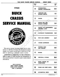
Section 4-B · Pages 93–106 (14 pages)
Synchromesh Transmission and Universal Joint
From the 1960 Buick Chassis Service Manual
Specifications, description and trouble diagnosis for the S-M synchromesh transmission, the steering column shift control mechanism, removal and installation of the transmission, torque ball and flywheel, and universal joint service.
Read this section free, starting at page 93What this section covers
- S-M transmission and universal joint specifications
- S-M transmission description
- Shift control mechanism
- Transmission trouble diagnosis
- Removal and installation of transmission and torque ball
- Year
- 1960
- Make
- Buick
- Vehicle
- Passenger Cars
- Type
- Service Manual
- Models
- LeSabre 4400, Invicta 4600, Electra 4700, Electra 225 4800
- Pages
- 429
What’s inside
Introduction
Lubrication
- 1-ALubricare Instructionspp. 7–17
- 1-BBearing Service (Ball and Roller)Removal, installation, cleaning, inspection and care of the ball and roller bearings used throughout the chassis units.pp. 18–20
Fuel and exhaust
- 3-AFuel System Specifications and Descriptionpp. 21–27
- 3-BFuel System Trouble DiagnosisDiagnosis of hard starting, improper engine performance and excessive fuel consumption, including advice on correct use of the accelerator pedal for starting.pp. 28–30
- 3-CAdjustments and Carburetor Assembliespp. 31–35
- 3-DFuel Pumppp. 36–39
- 3-ECarter 2-Barrel Carburetorpp. 40–50
- 3-FCarter 4-Barrel Carburetorpp. 51–60
- 3-GStromberg 2-Barrel Carburetorpp. 61–69
- 3-HRochester 4-Barrel Carburetorpp. 70–84
Clutch and transmission
- 4-AClutchpp. 85–92
- 4-BSynchromesh Transmission and Universal Jointpp. 93–106
Rear axle
- 6-ARear Axle Specifications, Description, Trouble Diagnosispp. 107–111
- 6-BRear Axle Service Procedurespp. 112–129
- 6-CPositive Traction Differentialpp. 130–141
Chassis suspension
- 7-BTrouble Diagnosis, Chassis Suspensionpp. 142–147
- 7-CService, Adjustment and Replacement Procedurespp. 148–164
Steering
- 8-AManual Steering Gear and Linkagepp. 165–173
- 8-BRotary Valve Power Steering Gear and Pumppp. 174–217
Brakes
Electrical systems
- 10-BElectrical Trouble Diagnosispp. 247–252
- 10-CBattery and Cablespp. 253–260
- 10-DGenerating Systempp. 261–274
- 10-ECranking (Starter) Systempp. 275–287
- 10-FIgnition Systempp. 288–301
- 10-GLighting Systempp. 302–320
- 10-HSignal Systemspp. 321–336
- 10-JWiring Circuit Diagramspp. 337–354
Radio, heater, air conditioner
Other manuals for this vehicle
 1929Specifications1929 Buick Detailed Specifications
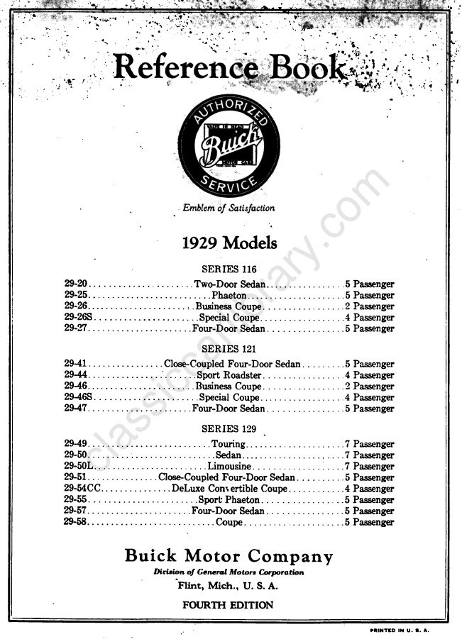 1929Owner's Manual1929 Buick Reference Book (Owner’s Manual)
 1933Service Manual1933 Buick Shop Manual
 1934Service Manual1934 Buick Series 40 Shop ManualBPS-1.19
 1934Service Manual1934 Buick Series 50 60 90 Shop ManualBPS-1.18
 1940Parts Catalog1940-1972 Buick Chassis and Body Illustration Catalog
 1940Parts Catalog1940–1955 GM Automatic Transmission Parts Catalog A-3010A-3010
 1942Service Manual1942 Buick Shop ManualBPS-1.27