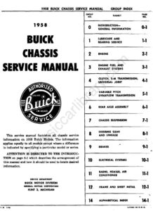
Section 12 · Pages 494–507 (14 pages)
Frame and Sheet Metal
From the 1958 Buick Chassis Service Manual
Checking frame and suspension alignment, frame repairs, body mountings for closed and convertible bodies, a description of the front end sheet metal, and fender, bumper and hood alignment, adjustment and replacement, with frame dimension drawings for Series 40-60 and 50-70.
Read this section free, starting at page 494What this section covers
- Checking frame alignment
- Frame repairs
- Body mountings
- Front end sheet metal
- Fender and bumper adjustment
- Hood adjustment and replacement
- Year
- 1958
- Make
- Buick
- Vehicle
- Passenger Cars
- Type
- Service Manual
- Models
- Series 40, 50, 60 and 70 (model numbers 46R, 48, 49, 49D, 61, 63, 69 named)
- Pages
- 511
What’s inside
Chassis service manual
- 0Introduction and General Informationpp. 3–6
- 1ALubricare Instructionspp. 7–18
- 1BBearing Service (Ball and Roller)pp. 19–22
- 2AEngine Specificationspp. 23–26
- 2BEngine Descriptionpp. 27–35
- 2CEngine Tune-Care and Trouble Diagnosispp. 36–41
- 2DCylinder Head and Valve Mechanism Servicepp. 42–49
- 2ECrankshaft and Connecting Rod Bearings, Pistons and Ringspp. 50–58
- 2FCooling and Oiling Systems Servicepp. 59–62
- 2GEngine Mounting, Flywheel Replacement and Engine Balancingpp. 63–66
- 3AFuel and Exhaust Specifications and Descriptionpp. 67–72
- 3BFuel System Trouble DiagnosisTrouble diagnosis charts for the fuel system, covering fuel feed, carburetor and related complaints such as hard starting and excessive fuel consumption.pp. 73–75
- 3CAdjustments and Replacementspp. 76–80
- 3DFuel Pumppp. 81–84
- 3ECarter 2-Barrel Carburetorpp. 85–95
- 3FCarter 4-Barrel Carburetorpp. 96–105
- 3GStromberg 2-Barrel Carburetorpp. 106–114
- 3HRochester 4-Barrel Carburetorpp. 115–128
- 4AClutchpp. 129–136
- 4BSynchromesh Transmission and Universal Jointpp. 137–150
- 5AVariable Pitch Dynaflow Specifications and Descriptionpp. 151–176
- 5BVariable Pitch Dynaflow Trouble Diagnosis and Adjustmentspp. 177–185
- 5CVariable Pitch Dynaflow Removal, Disassembly and Assemblypp. 186–216
- 6ARear Axle Specifications, Description and Trouble Diagnosispp. 217–221
- 6BRear Axle Service Procedurespp. 222–240
- 7AChassis Suspension Specifications and Descriptionpp. 241–245
- 7BChassis Suspension Trouble Diagnosispp. 246–251
- 7CChassis Suspension Service, Adjustment and Replacementpp. 252–267
- 7DAir-Poise Suspensionpp. 268–300
- 8AManual Steering Gear and Linkagepp. 301–309
- 8BPower Steering Gear and Pumppp. 310–334
- 9ABrake Specifications and Descriptionpp. 335–339
- 9BBrake Trouble Diagnosispp. 340–345
- 9CBrake Service, Adjustment and Repair Procedurespp. 346–356
- 9DPower Brakespp. 357–368
- 10AElectrical Systems Specificationspp. 369–372
- 10BElectrical Trouble Diagnosispp. 373–378
- 10CBattery and Cablespp. 379–386
- 10DGenerating Systempp. 387–400
- 10ECranking (Starter) Systempp. 401–413
- 10FIgnition Systempp. 414–427
- 10GLighting Systempp. 428–444
- 10HSignal Systemspp. 445–450
- 10IInstruments and Clockpp. 451–456
- 10JWiring Circuit Diagramspp. 457–462
- 11ARadiopp. 463–473
- 11BHeater and Air Conditionerpp. 474–493
- 12Frame and Sheet Metalpp. 494–507
Index
Other manuals for this vehicle
 1929Specifications1929 Buick Detailed Specifications
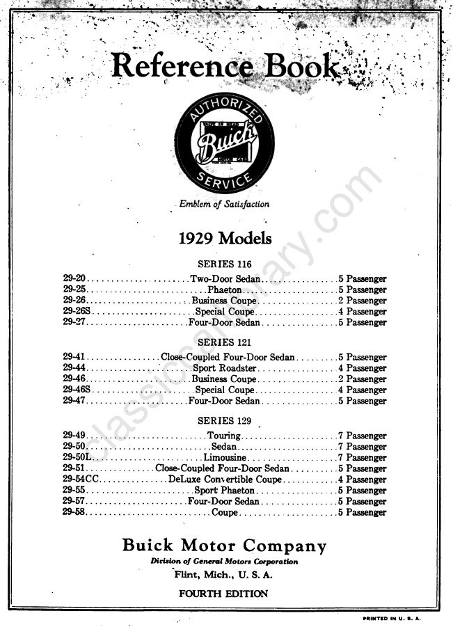 1929Owner's Manual1929 Buick Reference Book (Owner’s Manual)
 1933Service Manual1933 Buick Shop Manual
 1934Service Manual1934 Buick Series 40 Shop ManualBPS-1.19
 1934Service Manual1934 Buick Series 50 60 90 Shop ManualBPS-1.18
 1940Parts Catalog1940-1972 Buick Chassis and Body Illustration Catalog
 1940Parts Catalog1940–1955 GM Automatic Transmission Parts Catalog A-3010A-3010
 1942Service Manual1942 Buick Shop ManualBPS-1.27