Section 8 · Pages 168–181 (14 pages)
Brakes
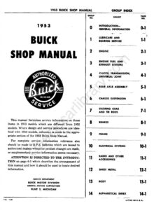
From the 1953 Buick Shop Manual
Brake changes for 1953 and the new power brakes, standard on the Model 76X Skylark and optional on Series 50 and 70. It describes the Kelsey-Hayes vacuum power brake cylinder, gives trouble diagnosis, removal, installation, adjustment and bleeding, and covers complete disassembly, inspection and assembly of the cylinder.
Read this section free, starting at page 168What this section covers
- Changes in brake mechanism
- Power brake cylinder construction and operation
- Power brake trouble diagnosis
- Removal, adjustment and bleeding
- Power brake cylinder overhaul
- Year
- 1953
- Make
- Buick
- Vehicle
- Passenger Cars
- Type
- Service Manual, Supplement
- Models
- Special Series 40, Super Series 50, Roadmaster Series 70 incl. Model 76X Skylark
- Pages
- 315
What’s inside
Shop manual
- 0Introduction and General Informationpp. 1–4
- 1Lubricare and Bearing Servicepp. 5–15
- 2-AEngine Specificationspp. 16–19
- 2-BEngine Descriptionpp. 20–29
- 2-CEngine Tune Up and Trouble Diagnosispp. 30–35
- 2-DCylinder Head and Valve Mechanism Servicepp. 36–44
- 2-ECrankshaft and Connecting Rod Bearings, Pistons and Ringspp. 45–52
- 2-FCooling and Oiling Systems Servicepp. 53–56
- 2-GV-8 Engine Mounting, Flywheel Replacement, Engine Balancingpp. 57–61
- 3-AFuel and Exhaust Specifications and General Descriptionpp. 62–67
- 3-BFuel System Trouble DiagnosisDiagnosis of hard starting, improper engine performance and excessive fuel consumption, with a gasoline mileage test procedure and expected miles per gallon at 20, 40 and 60 mph for each series.pp. 68–70
- 3-CAdjustments and Replacements Except in Pump and Carburetorpp. 71–75
- 3-DFuel and Vacuum Pumppp. 76–81
- 3-ECarter 2-Barrel Carburetor and Climatic Controlpp. 82–94
- 3-FCarter 4-Barrel Carburetorpp. 95–104
- 3-GStromberg 2-Barrel Carburetor and Automatic Chokepp. 105–117
- 3-HStromberg 4-Barrel Carburetorpp. 118–129
- 4Clutch, Transmission, Universal Jointpp. 130–147
- 5Rear Axle AssemblyRear axle changes for 1953: a new propeller shaft seal, revised pinion bearing lock nut and seal, the second-type differential carrier, gear ratios, and pinion removal and setting with tool J 5502 and gauge J 681-A.pp. 148–151
- 6Chassis Suspensionpp. 152–155
- 7Steering Gear and Tie Rodspp. 156–167
- 8Brakespp. 168–181
- 9Framepp. 182–185
- 10-AElectrical Specificationspp. 186–189
- 10-BElectrical Trouble Diagnosispp. 190–195
- 10-CBattery and Cablespp. 196–203
- 10-DGenerating Systempp. 204–219
- 10-ECranking (Starter) Systempp. 220–235
- 10-FIgnition Systempp. 236–250
- 10-GLighting Systempp. 251–258
- 10-HSignal Systemspp. 259–264
- 10-IInstruments and Clockpp. 265–268
- 10-JWiring Circuit Diagramspp. 269–276
- 11-AAccessories Except Radiopp. 277–280
- 11-BRadiopp. 281–296
- 12Sheet Metalpp. 297–302
- 13Bodypp. 303–312
- 14Alphabetical IndexAlphabetical subject index with group page numbers; subjects not listed are referred to the 1952 Buick Shop Manual.pp. 313–315
Other manuals for this vehicle
 1929Specifications1929 Buick Detailed Specifications
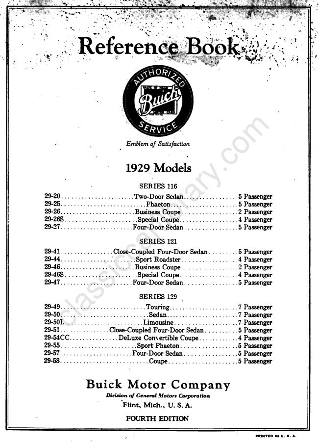 1929Owner's Manual1929 Buick Reference Book (Owner’s Manual)
 1933Service Manual1933 Buick Shop Manual
 1934Service Manual1934 Buick Series 40 Shop ManualBPS-1.19
 1934Service Manual1934 Buick Series 50 60 90 Shop ManualBPS-1.18
 1940Parts Catalog1940-1972 Buick Chassis and Body Illustration Catalog
 1940Parts Catalog1940–1955 GM Automatic Transmission Parts Catalog A-3010A-3010
 1942Service Manual1942 Buick Shop ManualBPS-1.27