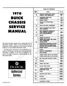
Section 80 · Pages 1035–1062 (28 pages)
Fuel Tank and Exhaust Systems
From the 1970 Buick Chassis Service Manual
Section A covers the fuel tank and fuel system, including tank venting, the evaporative emission control system with vapor line and accumulator, fuel gage tank unit removal and tank lowering for each series. Section B covers the exhaust system, with removal and installation of mufflers, resonators and pipes and exhaust system drawings for Skylark, GS, LeSabre, Wildcat, Electra, Estate Wagon and Riviera.
Read this section free, starting at page 1035What this section covers
- Fuel tank description and venting
- Evaporative emission control
- Fuel tank and gage unit removal
- Muffler and resonator replacement
- Exhaust system figures by model
- Year
- 1970
- Make
- Buick
- Type
- Service Manual
- Models
- Special, Skylark, GS, GS 455, LeSabre, Wildcat, Electra 225, Estate Wagon, Riviera (43-49000 series)
- Pages
- 1,430
What’s inside
Front matter
- Title Page, Contents and IntroductionTitle page and table of contents listing the groups and their first page numbers, the Buick Motor Division copyright page, and an introduction explaining how groups, sections, divisions and paragraphs are numbered, plus special tool references and how to find information.pp. 1–5
Chassis service groups
- 00General Information, Maintenance and Lubricationpp. 6–25
- 10Windshield Wiper and Washer Systempp. 26–69
- 12Heater Systempp. 70–95
- 13Heater and Air Conditioner Systempp. 96–244
- 20Frame and Body Mountingspp. 245–266
- 30Front Suspension and Front End Alignmentpp. 267–303
- 40Rear Suspension, Automatic Level Control, Propeller Shaft and Differentialpp. 304–425
- 50Brakespp. 426–519
- 60Engine Mechanicalpp. 520–610
- 64Engine Fuel System, Fuel Pumps and Carburetorspp. 611–676
- 65Cruise MasterDescription, operation and installation of the driver-operated Cruise Master speed control, engaged by a switch at the end of the directional signal lever. Covers engagement, disengagement, speed adjustment and override, the green cruise lamp, and installation drawings for the 43-44000 series.pp. 677–681
- 67Controlled Combustion Systempp. 682–699
- 68Engine Electrical: Generating, Starting and Ignitionpp. 700–739
- 69Engine Tune-Uppp. 740–744
- 71Clutchpp. 745–757
- 72Manual Transmissionspp. 758–815
- 73Shift Linkage Adjustmentspp. 816–832
- 75Turbo Hydra-Matic 350 Automatic Transmissionpp. 833–937
- 76Turbo Hydra-Matic 400 Automatic Transmissionpp. 938–1034
- 80Fuel Tank and Exhaust Systemspp. 1035–1062
- 90Steeringpp. 1063–1134
- 100Wheels and Tirespp. 1135–1154
- 110Chassis Sheet Metalpp. 1155–1194
- 120Chassis Electrical and Instrument Panelpp. 1195–1335
- 129Radio and Stereo Tape Playerpp. 1336–1352
- 130Radiators and Grillespp. 1353–1370
- 140Bumperspp. 1371–1392
- 150Accessoriespp. 1393–1420
Tables and index
- Decimal Equivalents, Drill Sizes and Alphabetical IndexReference tables for decimal equivalents, number and letter drill sizes with tap sizes, followed by the alphabetical index listing each subject with its group and page number, such as Air Conditioner, Alignment, Battery and Belt Tensions.pp. 1421–1430
Other manuals for this vehicle
 1940Parts Catalog1940-1972 Buick Chassis and Body Illustration Catalog
 1962Body Service Manual1962 Buick Body Service Manual
 1962Service Manual1962 Buick Special Chassis Service Manual
 1963Body Service Manual1963 Buick Body Service Manual
 1964Parts Catalog1964–1965 Buick Special Master Parts CatalogCatalogue No. 654-A
 1971Owner's Manual1971 Buick Skylark, GS and Sport Wagon Owner’s Manual1235773