
Section 6C · Pages 320–329 (10 pages)
Propeller Shaft
From the 1962 Buick Special Chassis Service Manual
Description, removal, disassembly, assembly and installation of the two-piece propeller shaft with its center support bearing and universal joints, plus rear universal joint angle adjustment.
Read this section free, starting at page 320What this section covers
- Propeller shaft description
- Removal of propeller shaft
- Disassembly and assembly
- Center support bearing
- Rear universal joint angle
- Year
- 1962
- Make
- Buick
- Type
- Service Manual
- Models
- Series 4000, 4100 and 4300 Special (V-6 and aluminum V-8)
- Pages
- 675
What’s inside
Chassis service manual
- 0Introduction and General InformationHow the manual is organized into groups, sections and paragraphs, the new car warranty, the 1962 Special model list (4019 through 4347), general dimensions and how to read the vehicle and engine identification numbers.pp. 3–5
- 1Lubricare Instructionspp. 6–19
- 2AEngine Specificationspp. 20–26
- 2BEngine Descriptionpp. 27–36
- 2CEngine Tune-Care and Trouble Diagnosispp. 37–42
- 2DCylinder Head and Valve Mechanism Servicepp. 43–56
- 2EReplacement of Crankshaft and Connecting Rod Bearings, Pistons and Ringspp. 57–66
- 2FCooling and Oiling Systems Servicepp. 67–73
- 2GEngine Mounting, Flywheel and Thread Repairpp. 74–78
- 3AFuel and Exhaust Specifications and Descriptionpp. 79–86
- 3BFuel System Trouble DiagnosisCauses and corrections for hard starting, improper engine performance and excessive fuel consumption, including starting technique, choke adjustment and fuel supply faults.pp. 87–89
- 3CAdjustments and Replacements Except Pump and Carburetorpp. 90–95
- 3DFuel Pumppp. 96–99
- 3ERochester 2-Barrel Carburetorpp. 100–109
- 3FRochester 4-Barrel Carburetorpp. 110–123
- 4AClutchpp. 124–130
- 4BSynchromesh Transmissionpp. 131–148
- 4C4-Speed Transmissionpp. 149–165
- 5AAutomatic Transmission Specifications, Description and Operationpp. 166–202
- 5BAdjustments On Car and Road TestOn-car throttle linkage and manual control adjustments for the automatic transmission, followed by the road test procedure.pp. 203–204
- 5CAutomatic Transmission Removal, Disassembly and Assemblypp. 205–300
- 6ARear Axle Specifications and Descriptionpp. 301–306
- 6BRear Axle Service Procedurespp. 307–319
- 6CPropeller Shaftpp. 320–329
- 6DPositive Traction Differentialpp. 330–337
- 7AChassis Suspension Specifications and Descriptionpp. 338–341
- 7BChassis Suspension Trouble DiagnosisDiagnosis of car roughness or vibration, improper steering action and wheel tramp.pp. 342–343
- 7CService, Adjustment and Replacement Procedurespp. 344–362
- 8AManual Steering Gear and Linkagepp. 363–376
- 8BPower Steering Gear and Pumppp. 377–415
- 8CMast Jacket Assemblypp. 416–426
- 9ABrake Specifications, Description and Operationpp. 427–435
- 9BBrake Trouble Diagnosispp. 436–439
- 9CBrake Service, Adjustment and Repairpp. 440–449
- 9DPower Brakespp. 450–464
- 10AElectrical Specificationspp. 465–469
- 10BBattery and Cablespp. 470–478
- 10CGenerating Systempp. 479–490
- 10DCranking (Starter) Systempp. 491–500
- 10EIgnition Systempp. 501–516
- 10FLighting Systempp. 517–525
- 10GSignal Systemspp. 526–532
- 10HInstruments and Clockpp. 533–544
- 10IPolice Car Generating Systempp. 545–560
- 10JWiring Circuit Diagramspp. 561–578
- 11ARadiopp. 579–590
- 11BHeater and Ventilationpp. 591–599
- 11CAir Conditionerpp. 600–653
- 12Sheet Metal and Bumperspp. 654–667
Index
Other manuals for this vehicle
 1940Parts Catalog1940-1972 Buick Chassis and Body Illustration Catalog
 1962Body Service Manual1962 Buick Body Service Manual
 1963Body Service Manual1963 Buick Body Service Manual
 1964Parts Catalog1964–1965 Buick Special Master Parts CatalogCatalogue No. 654-A
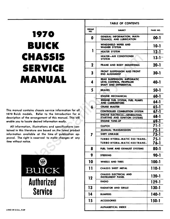 1970Service Manual1970 Buick Chassis Service Manual
 1971Owner's Manual1971 Buick Skylark, GS and Sport Wagon Owner’s Manual1235773